Electronics
By far the most daunting part of the printer build for many is wiring up the electronics bay of the printer. But fear not, many have preceeded you on this quest!
A word on safety
You will be working with mains voltages (120 VAC / 240 VAC). Always double check to make sure your printer is unplugged and that the capacitors in the power supplies are depleted (check the status LED) before touching any of the electronics.
Glossary
Working with electrical wiring and electronics can be confusing due to the plethora of acronyms and shorthands used. Here, we go over the most commonly used acronyms and shorthands within the 3D-printing community.
Connections / pads glossary
| Term | Description | Category | Note |
|---|---|---|---|
| L | Live | AC mains | no touchy |
| P1 | Live phase 1 | AC mains | no touchy |
| N | Neutral | AC mains | |
| PE | Protective earth | AC mains | Not the same as ground |
| VAC | Volts AC | AC mains | |
| VDC | Volts DC | DC voltages | |
| VCC | Voltage Collector | DC voltages | Derived from BJT Collector voltage |
| GND | Ground | DC voltages | a.k.a. Circuit ground |
| AGND | Analog Ground | DC voltages | Used for analog circuitry |
| VMOT | Motor voltage | DC voltages | Voltage for stepper drivers |
Electronics glossary
| Term | Description | Category | Note |
|---|---|---|---|
| Cap | Capacitor | Components | Stores and releases energy |
| JST | Wire terminal | Terminals | Japan Solderless Terminal |
| CSI | Camera Serial Interface | Connections | RPi-exclusive camera connector |
| DSI | Display Serial Interface | Connections | RPi-exclusive display connector |
| PSU | Power Supply Unit | Components |
Useful tools
| Tool | Purpose | Importance | Note |
|---|---|---|---|
| Ferrules | Terminating stranded wire | High | |
| Crimping pliers | Crimping various terminals | Medium | Required for JST, Ferrules, etc |
| Soldering iron | Soldering wire extensions etc | High | Better than twisting |
Wiring
To start you off, here are some miscellaneous tips you might need on your journey:
- You don’t need fancy tools to do electronics wiring, but it does make life more easy.
- Practice crimping (JST) connectors and ferrules and make them pass the “tug test”; this will save you a lot of headaches later!
- It is good practice to stick to the wire color conventions specific to your region.
You can of course use any wire color you want, but this may make it harder to troubleshoot later. - Avoid twisting wires together if soldering is an option
Twisted wire connections just aren’t very durable or safe for high intensity applications. - Don’t use silicone insulated wire in drag chains
The excess friction causes the drag chain to not work properly and wear your wires prematurely.
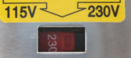
Make sure you’ve set the input voltage selector switch on your PSUs if applicable!
- Selecting 220V in a 110V country will cause your PSU to run under its rated power.
- Selecting 110V in a 220V country will cause your PSU to spontaneously have an existential crisis (it breaks).
AC wire color conventions
Different countries have different standards for mains wiring and the used colours, but these are the most prevalent ones you may want to know of according to the DIN 40705 and CEI/IEC 60446 standards:
| Wire & cable | US/Canada | Europe & UK | China & Russia | Oceania | Japan | India |
|---|---|---|---|---|---|---|
| Live / Line |
 
|
 |
 |
|
|
|
| Neutral |
 
|
 |
|
|
|
|
| Ground / Earth |
 
|
|
|
|
|
|
AC Power Inlet Europe & UK 220V
This is how to wire the power inlet for 220V. The optional wire is solely for lighting up the LED in the switch. 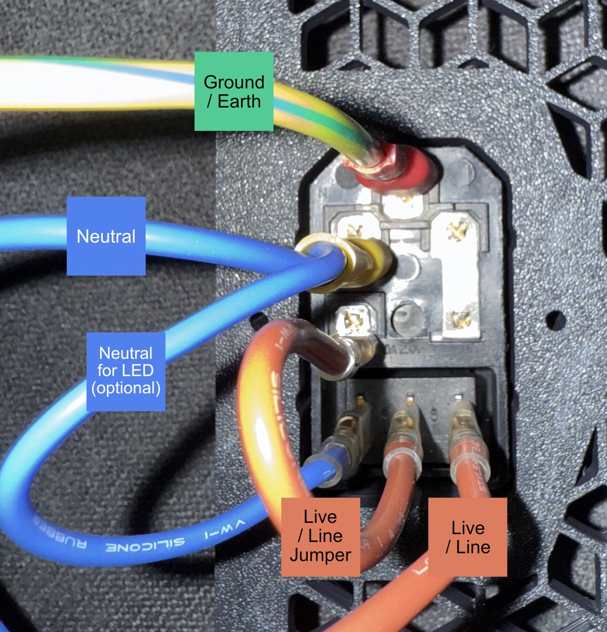
DC wire color conventions
There is no general standard for what colours are used for what voltage node, but there are some key standard colours we like to abide by in the 3D-printing community (derived from the ATX colour coding standard).
| Potential | Symbol | Colour | Note |
|---|---|---|---|
| Ground | GND |
|
|
| 5V | 5V |
|
For supply lines |
| Signals |
S, Signal
|
|
For signals such as limit switches |
| 12V | 12V |
|
|
| 24V |
24V, VCC, VMOT, etc. |
|
|
| 48V |
48V, HT, VMOT, etc. |
 
|
Use a color different from 5V/24V |
Choosing the correct wire type
Using smaller wires than recommended for their rated current may result in cables melting or catching fire. Always use a wire gauge that at least matches the current load!
Using appropriately sized wires ensures they can safely handle the current draw of your printer’s components. Using undersized wires will increase the wire’s electrical losses, which can lead to (over)heating, damage to the wires or your printer, or even other things. Undersized wiring is always an imminent fire hazard for this reason.
Recommended wire gauges
This table specifies recommended minimum wire size when using nickle-free stranded copper wires; larger wire can always be used (within reasonable limits).
The rated current capacities are a general rule of thumb. Ensure wires are never used beyond their rated specifications! This includes (but is not limited to): current rating, resistance per length, insulation temperature limit, and environmental temperature. The Standard Wire Gauge or American Wire Gauge engineering tables contain more reference information.
| Application | AWG | Metric | Max current rating |
|---|---|---|---|
| Mains / AC | 18 AWG | 0.75 mm² | 10A @ 120/240VAC |
| Hotend heater | 20 AWG | 0.50 mm² | 6A @ 12-24VDC |
| Stepper motors | 22 AWG | 0.32 mm² | 4A @ 12-48VDC |
| Signal wires | 24 AWG | 0.20 mm² | 2A @ 5-24VDC |
Mantle types
In general, it is recommended to use stranded copper cable for most DC components. For motion components, always use a motion rated stranded copper cable, with a mantle suitable for motion applications. Good wire options are silicone sleeved cables or PTFE (teflon) sleeved cables that come at an extra cost, but are more flexible and provide less friction inside a wire loom.