3.1 Motor mounts + integrated hinges
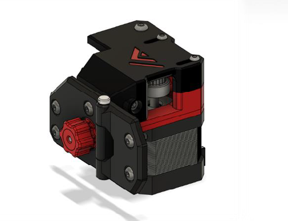
Overview
BOM
| Material | Quantity | Notes |
|---|---|---|
| M3 6mm (countersunk) | 6 | - |
| M3 35mm | 4 | - |
| M4 10mm | 12 | - |
| M4 8mm (countersunk) | 2 | - |
| M4 30mm (hex bolt) | 2 | - |
| M4 40mm (barrelhead) | 2 | - |
| M4 t-nut | 10 | - |
| M4 nut | 8 | (also, for hinges) |
| 4mm ID washer | 2 | - |
| NEMA 17 | 2 | - |
| GT2 20T Pulley | 2 | - |
STL’s
| File name | Amount to print |
|---|---|
| Motor mount Part A | Left + Right |
| Motor mount Part B | Left + Right |
| X tensioner | Left + Right |
| Tensioner knob | 2 |
| CAP | 2 |
| Integrated hinge | 2 |
| Hinge/motor reinforcement | Left + Right |
Step 1
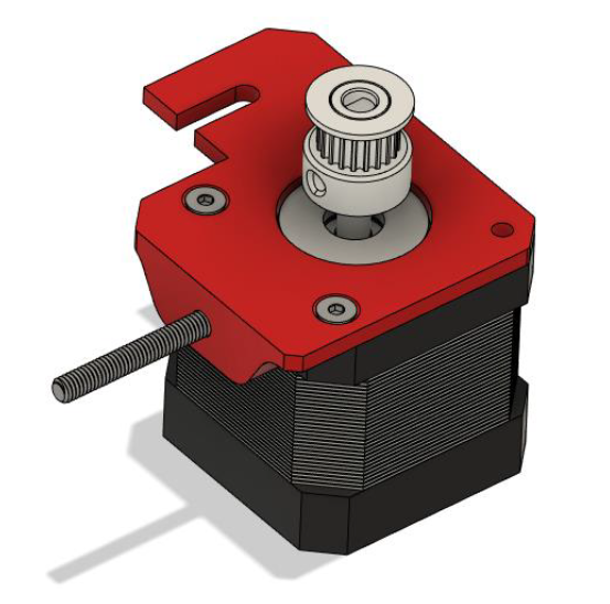
First attach the printed tensioner to the motor like shown above
Step 2
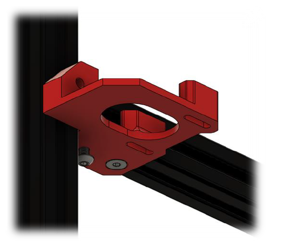
Then attach the lower bracket of the motor mount to the frame
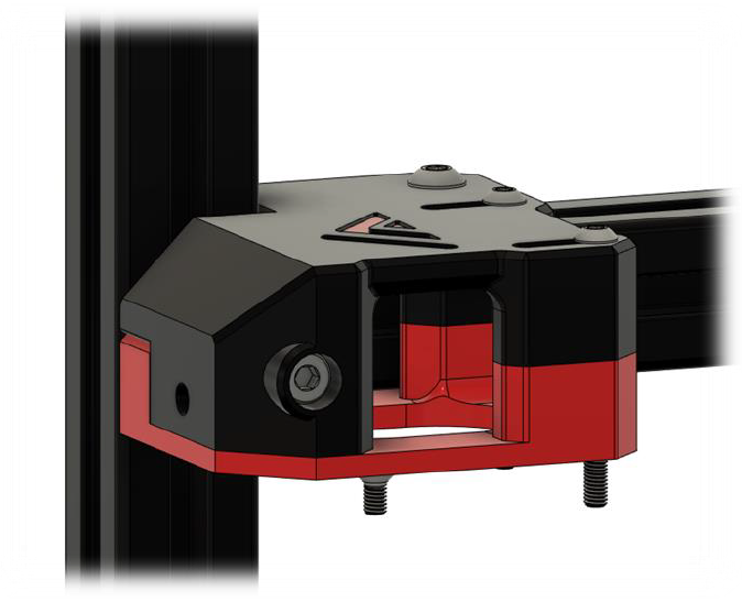
Step 3
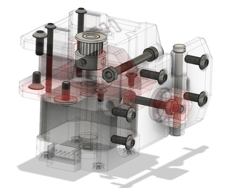
Insert the M4 nut in the upper half of the motor mount and attach it on top of the lower mount and to the frame with M4 T-nuts. Don’t forget to tighten the two halves to the frame by screwing down the 40mm M4 into the printed M4 holder you inserted when assembling the frame.
Step 4
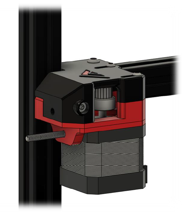
Attach the lowest part of the tensioner and motor, screw down the M4 in which the tensioner slides until it is snug, but the tensioner can still slide smoothly.
Step 5
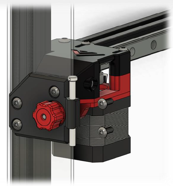
Finally attach the small side panel piece and attach the front brace/integrated hinge and tensioner knob. The hinge and door assembly can also be installed now but for ease of working it is best to leave it off for now.
Step 6
Repeat for the other side