2.1 Lower rod & leadscrew bracket
Overview
BOM
| Material | Quantity | Notes |
|---|---|---|
| M4 10mm | 10 | - |
| M4 12mm | 16 | - |
| M4 t-nut | 20 | - |
| 608-2RS bearings | 4 | - |
| 10mm rods ( 300mm ) | 4 | - |
| Belt GT2 closed ( 860mm ) | 1 | - |
| Leadscrew TR8 ( 300 mm ) | 2 | - |
| GT2 40 teeth | 2 | - |
| GT2 20 teeth | 1 | - |
STL’s
| File name | Amount to print |
|---|---|
| Z alignment tool | 2 |
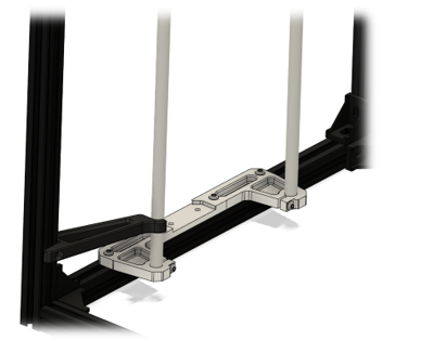
Step 1
Mount the top bracket with the 12mm M4 hardware to the frame loosely. Then mount the sliding rods with 12mm M4 screws and align the assembly to the frame using the printed “Z assembly alignment tool”. Be sure to secure all hardware. Be sure to either insert 2 T-nuts underneath the center two holes for the top leadscrew bracket or immediately mount the top bracket.
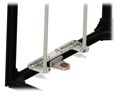
Step 2
Mount the lower leadscrew bracket, using 2x 10mm M4 screws, loosely to the frame approximately in the correct position relative to the top bracket.
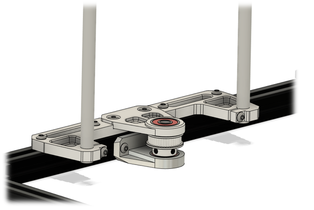
Step 3
Mount the top leadscrew bracket to the assembly using 12mm M4 screws (skip when done in step one). Insert the pulley with the closed belt and insert the leadscrew. Then tighten the grub screws on the pulley. Lastly while making sure the leadscrew is perfectly straight up tighten the screws on the upper and lower leadscrew brackets. This can be checked by measuring the distance on both sides between the leadscrew (top position) and the 10mm Rods.
Step 4
Repeat Step 1 / Step 2 / Step 3 for the other side of the frame