2. Frame
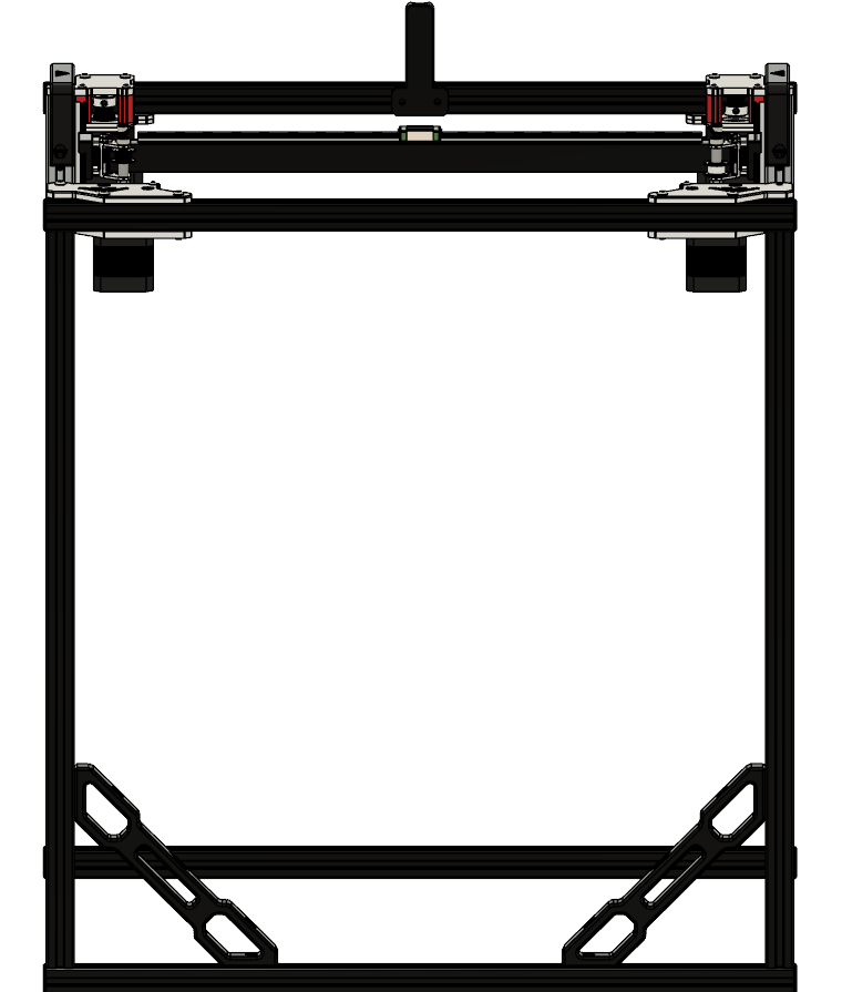 |
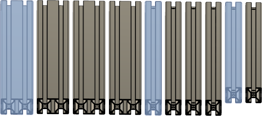
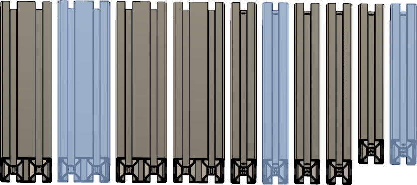
Parts
| Part | Location | Info |
|---|---|---|
| 2040 extrusion (530) Quantity: 4 |
Layer: 2 | 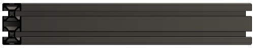 |
| 2020 extrusion (530mm) with two holes Quantity: 2 |
Layer: 2 |  |
| 2020 extrusion (460mm) with two holes Quantity: 2 |
Layer: 2 |  |
| Preasembled gantry Quantity: 1 |
Layer: 1 | |
| 2020 Corner brackets Quantity: 1 |
optional ( self sourced ) | |
| M5 x 25mm Quantity: 16 |
Layer: 3 Box: VZ330 Box 6 |
|
| M4 t-nut Quantity: 10 |
Layer: 3 Box: VZ330 Box 6 |
|
| M4 x 10mm Quantity: 8 |
Layer: 3 Box: VZ330 Box 6 |
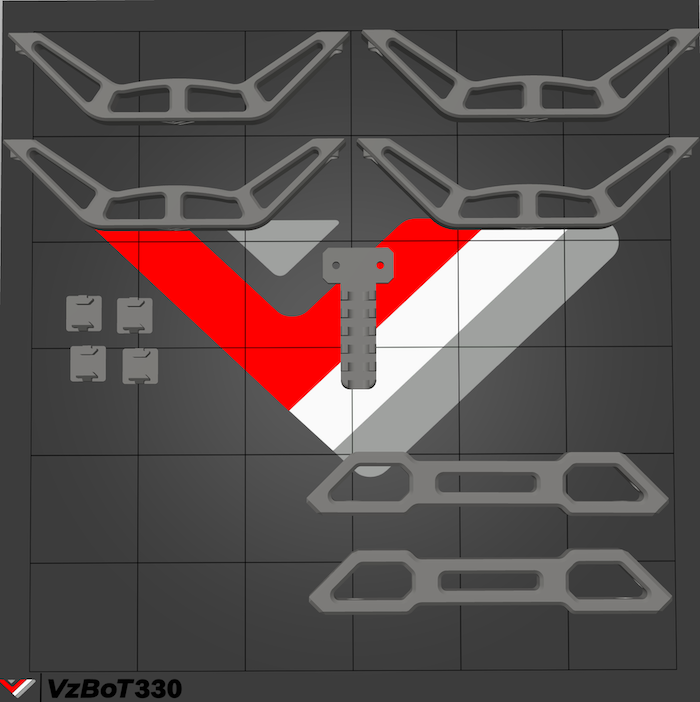
STLs
You can click on the object you wanna print on the plate and the corresponding STL will open up.
Video tutorial
Vz235 Build Part 1: The Frame
0:45 Cutting the frame to size
1:17 The frame
1:24 Parts
4:44 Water cooling kit
6:04 Acrylic panels
6:49 Aluminium parts
19:00 Bottom plate
Step 1
Make sure to use Loctite Blue on the bolts holding together the frame.
 |
| Part | Location |
|---|---|
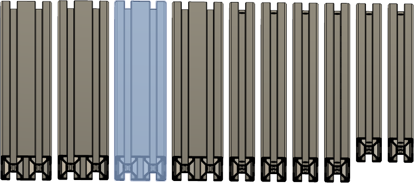
| 2040 extrusion ( 530 mm ) Quantity: 1 |
Layer: 2 |
| 2020 extrusion ( 530mm ) with two holes Quantity: 1 |
Layer: 2 |
| 2020 extrusion ( 460 mm ) with two holes Quantity: 1 |
Layer: 2 |
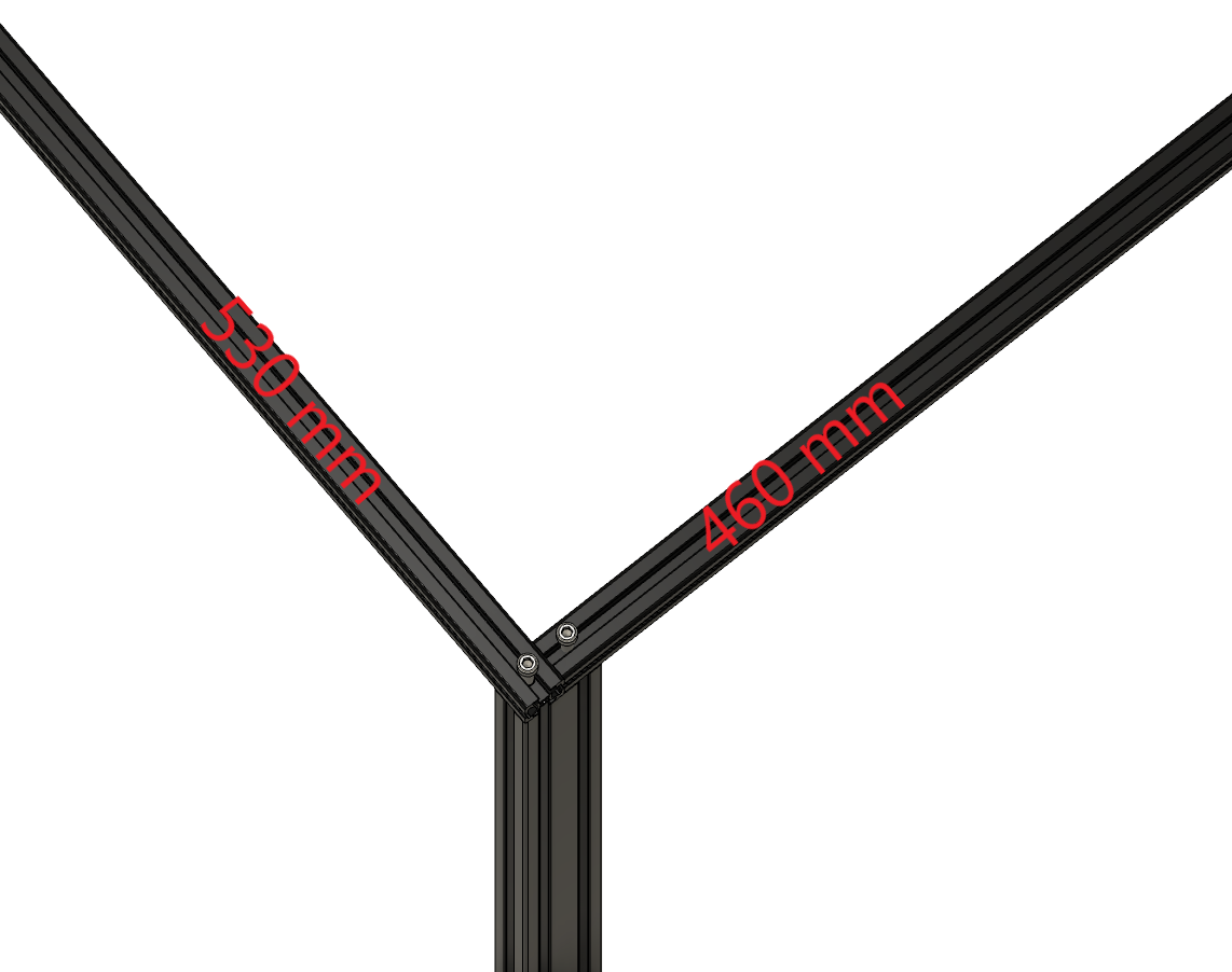 |
• Align the extrusions flush |
 |
• Tighten the 2020 extrusion’s to the 2040 extrusion |
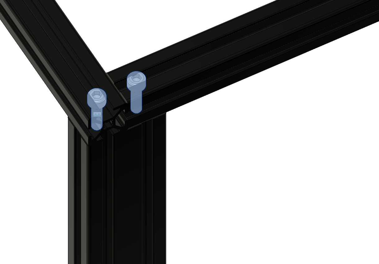
Step 2
Required
• Box 6 - M5 x 25mm
 |
| Part | Location |
|---|---|
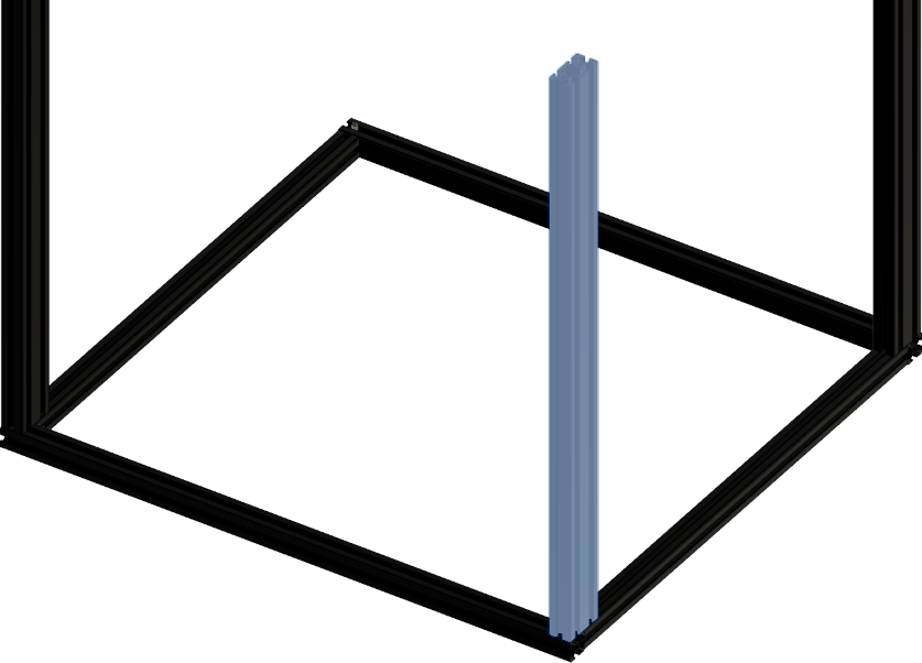
| 2040 extrusion ( 530mm ) Quantity: 1 |
Layer: 2 |
| 2020 extrusion ( 530mm ) with two holes Quantity: 1 |
Layer: 2 |
| 2020 extrusion ( 460mm ) with two holes Quantity: 1 |
Layer: 2 |
| M5 x 25mm Quantity: 2 |
Layer: 3 Box: VZ330 Box 6 |
 |
• Align the extrusions flush |
 |
• Tighten the 2020 extrusion’s to the 2040 extrusion |
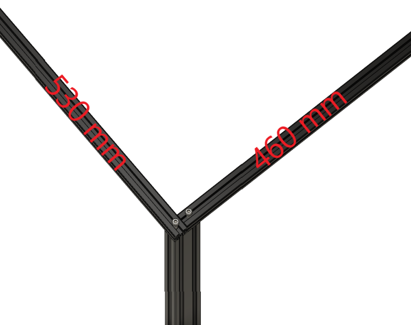
Step 3
Required
• Box 6 - M5 x 25mm
 |
| Part | Location |
|---|---|
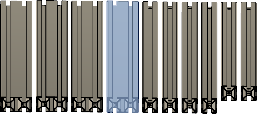
| 2040 extrusion ( 530mm ) Quantity: 1 |
Layer: 2 |
| Assembly from Step 1 / 2 Quantity: 1 |
Part from step 2 |
| M5 x 25mm Quantity: 2 |
Layer: 3 Box: VZ330 Box 6 |
 |
• Align the extrusions flush with the both 2020 extrusion’s |
|
• Tighten the 2020 extrusion’s to the 2040 extrusion |
Step 4
Required
• Box 6 - M5 x 25mm
 |
| Part | Location |
|---|---|
| 2040 extrusion (530mm) Quantity: 1 |
Layer: 2 |
| Assembly from Step 3 Quantity: 1 |
Part from step 3 |
| M5 x 25mm Quantity: 1 |
Layer: 3 Box: VZ330 Box 6 |
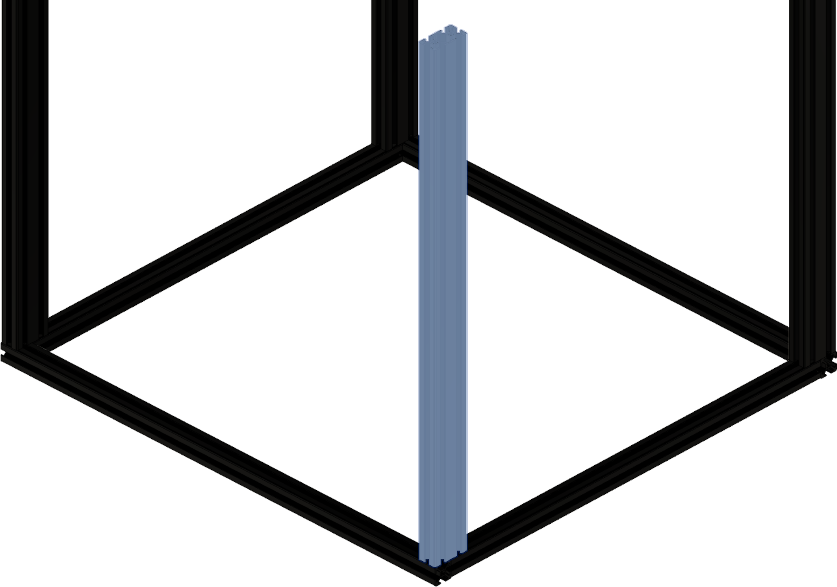 |
• Align the extrusions flush with the both 2020 extrusion’s |
 |
• Tighten the 2020 extrusion’s to the 2040 extrusion |
Step 5
| Part | Location |
|---|---|
| Preasembled gantry Quantity: 1 |
Layer: 1 |
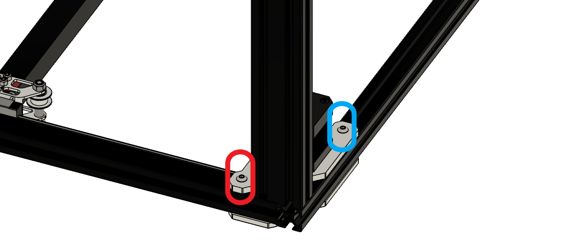 
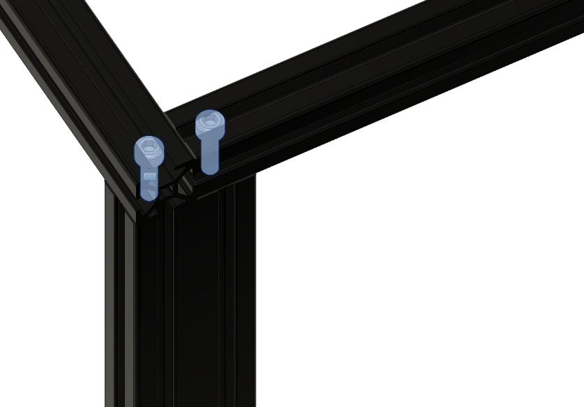
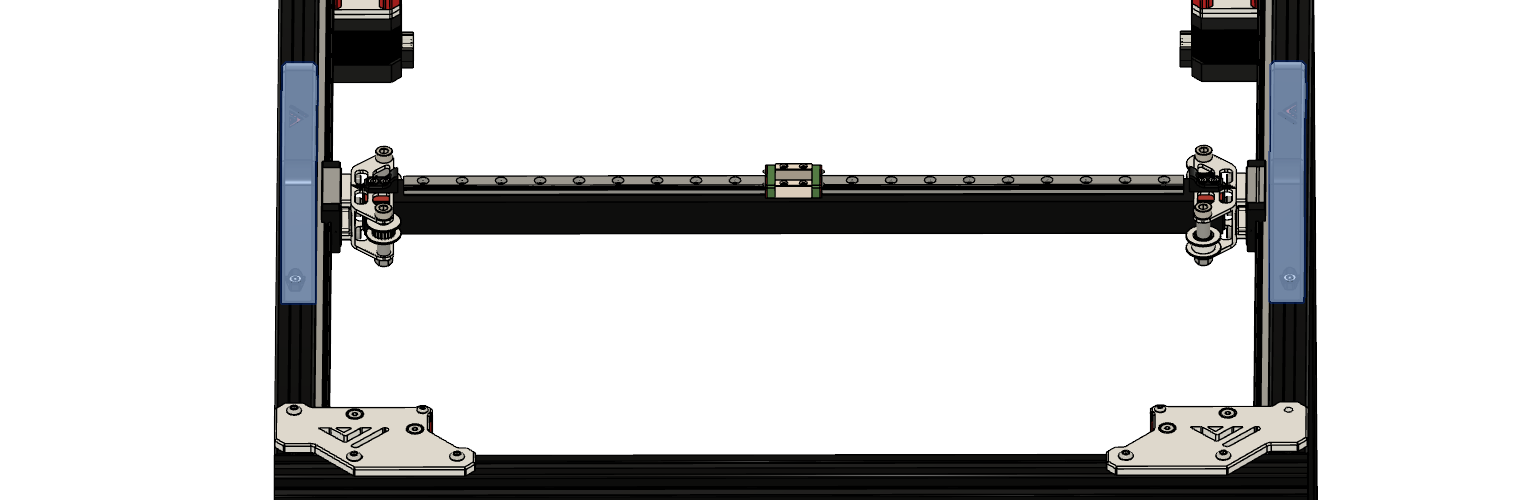
|
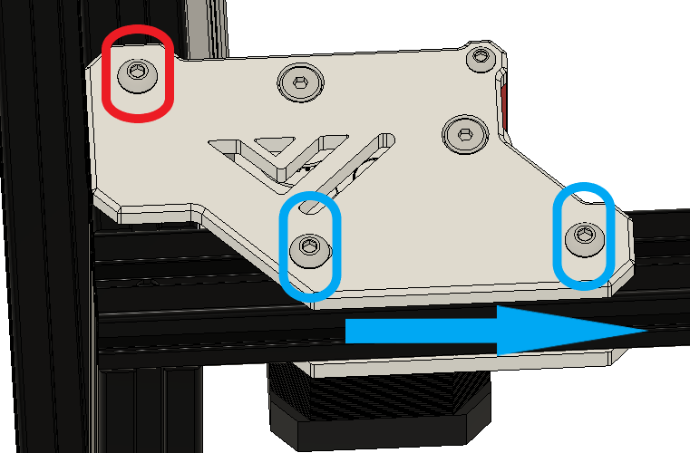
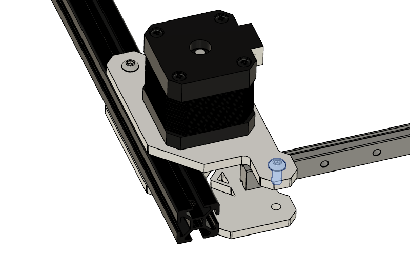
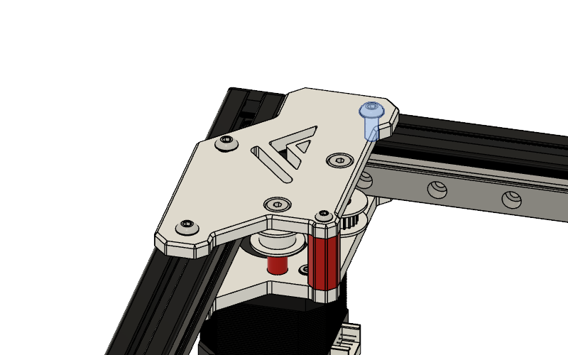
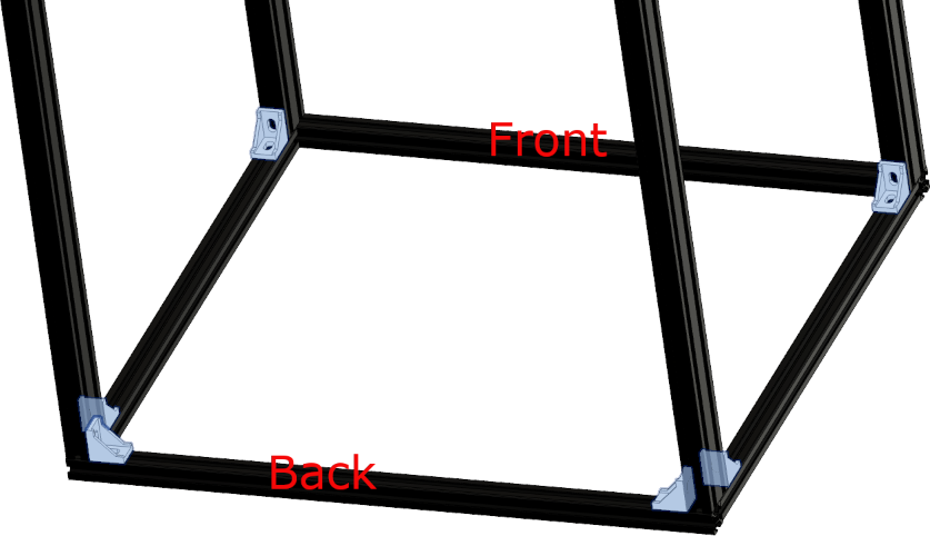
• Remove red marked screw • Losen blue screw • Slide assembly to the left • Remove the printed 2040 extrusion |
|
• Remove red marked screw • Losen blue screw • Slide assembly to the right • Remove the printed 2040 extrusion |
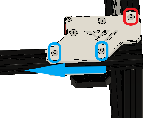
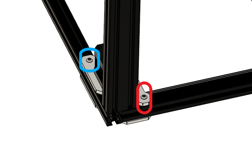
 |
• Remove selected part from assembly |
 |
• Remove printed 2040 extrusion part from the assembly |
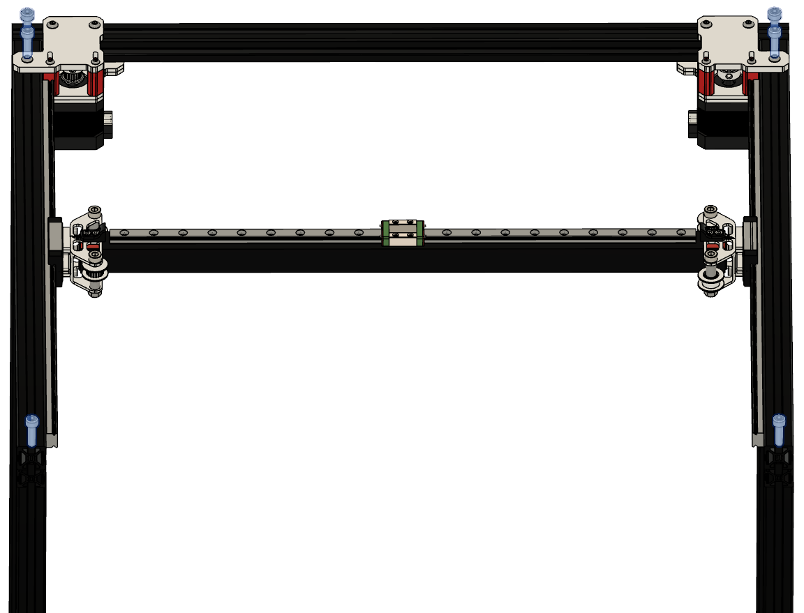 |
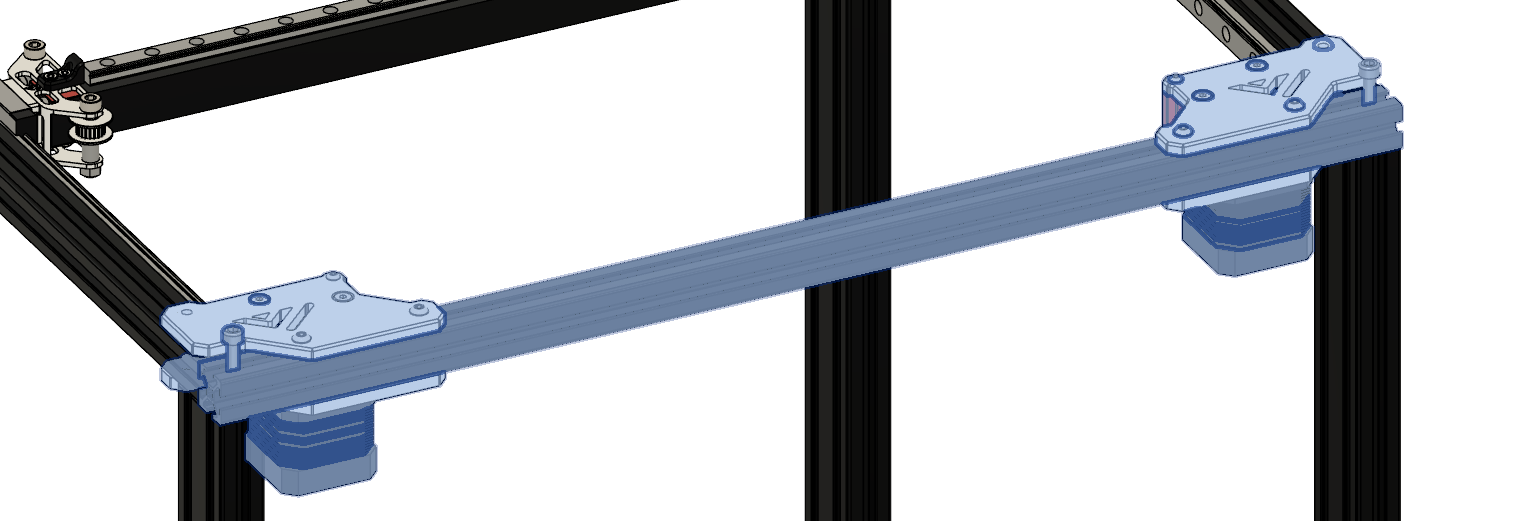
• Put preassembled assembly on the frame • Loosen all screws on the back motor mounts • Align extrusions • Screw down M5 x 25mm screws • Tighten screws on the motor mount again |
 |
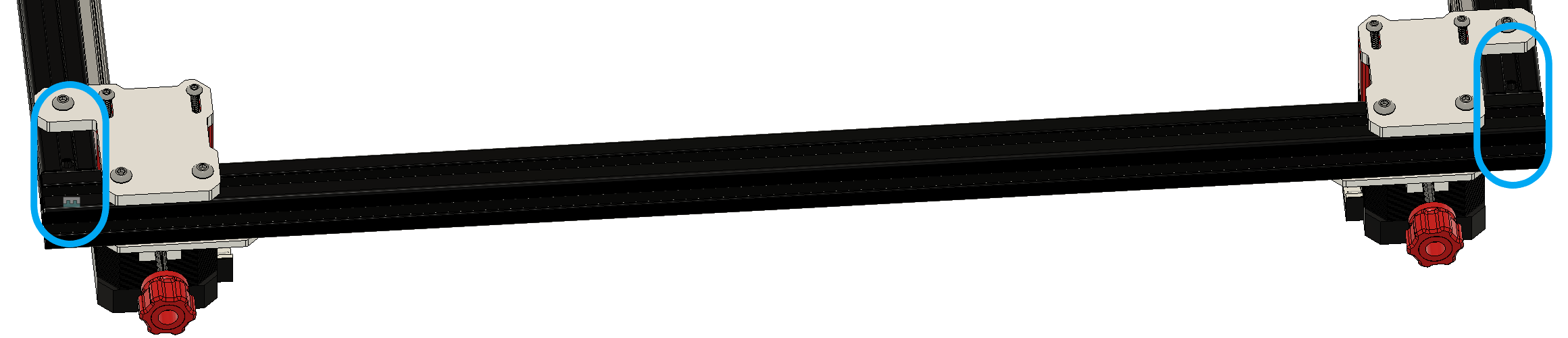
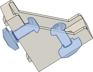
• Add screw + t-nut to the bottom part of the idler on the left and right side. |
 |
• Put second part on the frame • Align extrusions • Screw down M5x25mm screws |
 |
• Insert M4 Screw + t-nut in the upper part on the right / left side • Tighten the front motor mounts |
Step 6 (optional)
| Part | Location |
|---|---|
| 2020 corner brackets Quantity: 6 |
- |
| M4 x 10mm Quantity: 12 |
- |
| M4 t-nut Quantity: 12 |
- |
 |
• Insert screws and add t-nut |
 |
• Attach corner brackets to the frame, at the shown locations |
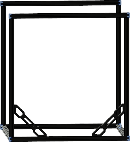
Step 7
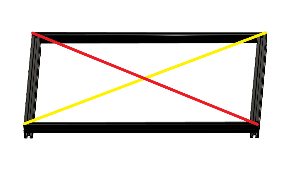 |
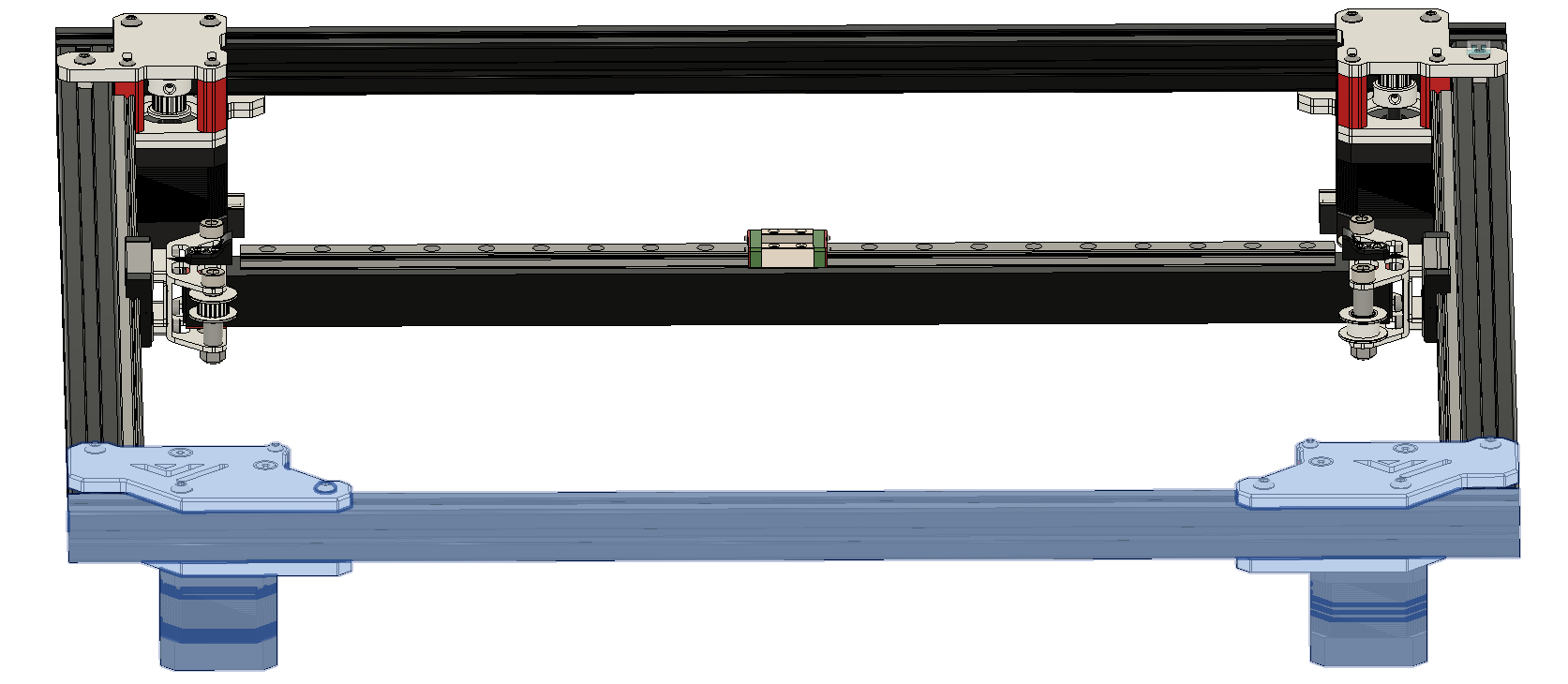
• Meassure from corner to corner ( yellow and red line ) • The distance should be the same for the red and the yellow line. • Do this for all side’s of the printer |
Step 8
Required
• Box 6 - M4 x 10mm
• Box 6 - M4 t-nut
| Part | Location |
|---|---|
| M4 x 10mm Quantity: 4 |
Layer: 3 Box: VZ330 Box 6 |
| M4 t-nut Quantity: 4 |
Layer: 3 Box: VZ330 Box 6 |
| Printed frame bracers Quantity: 2 |
STLs |
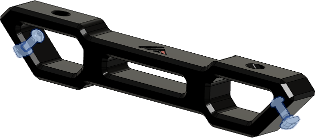 |
• Insert screws and add t-nut for both parts |
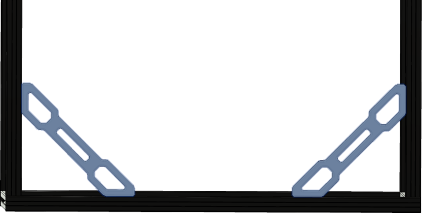 |
• Attach frame bracers to the frame in the front left and right |
Step 9
Required
• Box 6 - M4 x 10mm
• Box 6 - M4 t-nut
| Part | Location |
|---|---|
| M4 x 10mm Quantity: 4 |
Layer: 3 Box: VZ330 Box 6 |
| M4 t-nut Quantity: 4 |
Layer: 3 Box: VZ330 Box 6 |
| Printed handles Quantity: 2 |
STLs |
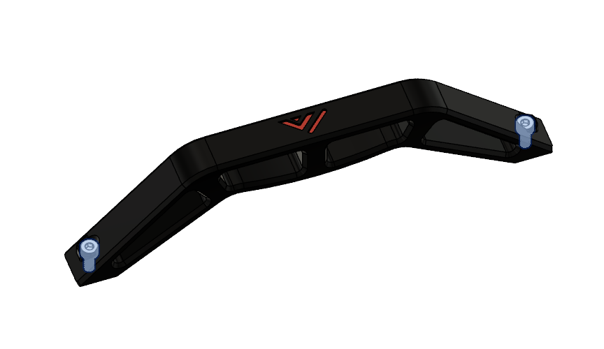 |
• Insert screws and add t-nut for both parts |
 |
• Attach handles to the left and right side of the frame and center them |
Step 10
Required
• Box 6 - M4 x 10mm
• Box 6 - M4 t-nut
| Part | Location |
|---|---|
| M4 x 10mm Quantity: 4 |
Layer: 3 Box: VZ330 Box 6 |
| M4 t-nut Quantity: 4 |
Layer: 3 Box: VZ330 Box 6 |
| Printed cable holder Quantity: 2 |
STLs |
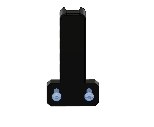 |
• Insert screws and add t-nut |
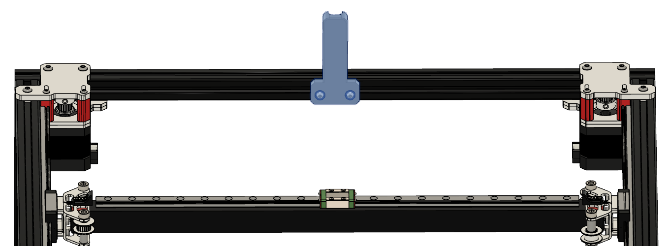 |
• Attach cable holder to the back of the frame and center it. |
Step 11
| Part | Location |
|---|---|
| Printed endpart’s Quantity: 8 |
STLs |
 |
• Insert all 8 endpart’s at the shown location. |
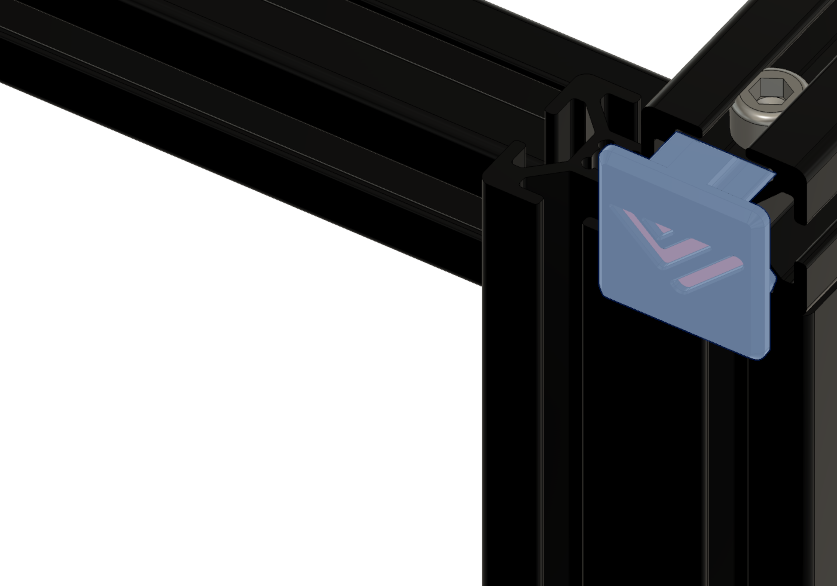 |
• Put in the endpart’s |