4.3 Printhead
In this section we’ll assemble the Toolhead for the VzBot.
Use Loctite Purple 222/221 for the bolts in the toolhead.
Parts
| Part | Location | Info |
|---|---|---|
| M3 x 6mm Quantity: 4 |
Layer: 3 Box: VZ330 Box 6 |
|
| TODO |
STLs
| File name | Amount to print | Note |
|---|---|---|
| X end stop switch mount | 1 | - |
| Cable Holder | 1 | - |
| Fan duct Goliath | 1 | Pick this if no beacon is used |
| Fan duct Goliath (beacon) | 1 | Use this duct for Goliath and beacon |
| Fan duct Goliath spacers | 2 | - |
| Fan duct upper | 1 | - |
| Upper duct mount | 1 | - |
| Upper duct CPAP c-clamp | 1 | - |
| Goliath 2510 fan duct | 1 | - |
Step 1
Required
• Box 6 - M3 x 6mm
• Box C
| Part | Location |
|---|---|
| M3 x 6mm Quantity: 4 |
Layer: 3 Box: VZ330 Box 6 |
| Back part of printhead |
Layer: 3 Box: VZ330 Box C |
| Cable Holder | STLs |
| Printhead cable holder | STLs |
 |
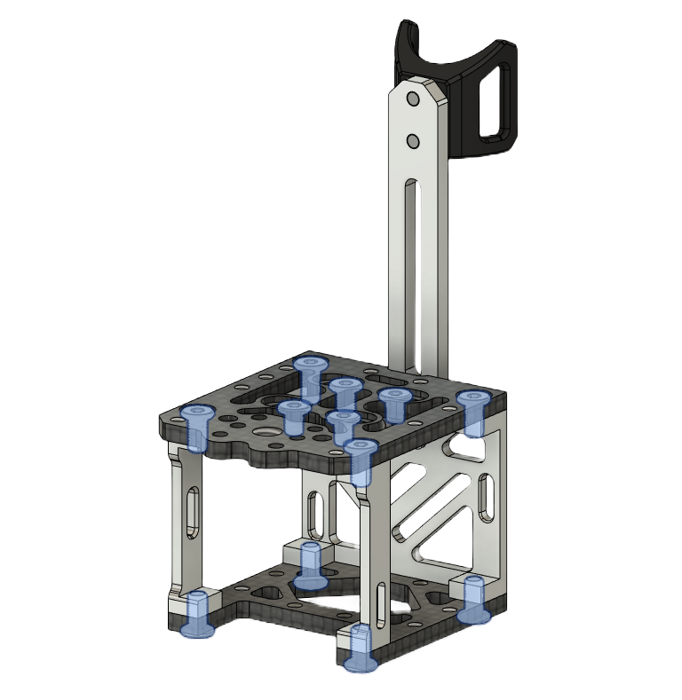
• Screw on the printhead cable holder with two M3 x 6mm screws • Attach the printed cable holder to the top with two M3 x 6mm screws. |
Step 2
Required
• Box 6 - M3 x 6mm
• Box 6 - M3 x 5mm
• Box C
| Part | Location |
|---|---|
| M3 x 6mm Quantity: 8 |
Layer: 3 Box: VZ330 Box 6 |
| M3 x 5mm Quantity: 4 |
Layer: 3 Box: VZ330 Box 6 |
| Part from step 1 | Part from step 1 |
| Top plate |
Layer: 3 Box: VZ330 Box C |
| Bottom plate |
Layer: 3 Box: VZ330 Box C |
| Side pieces |
Layer: 3 Box: VZ330 Box C |
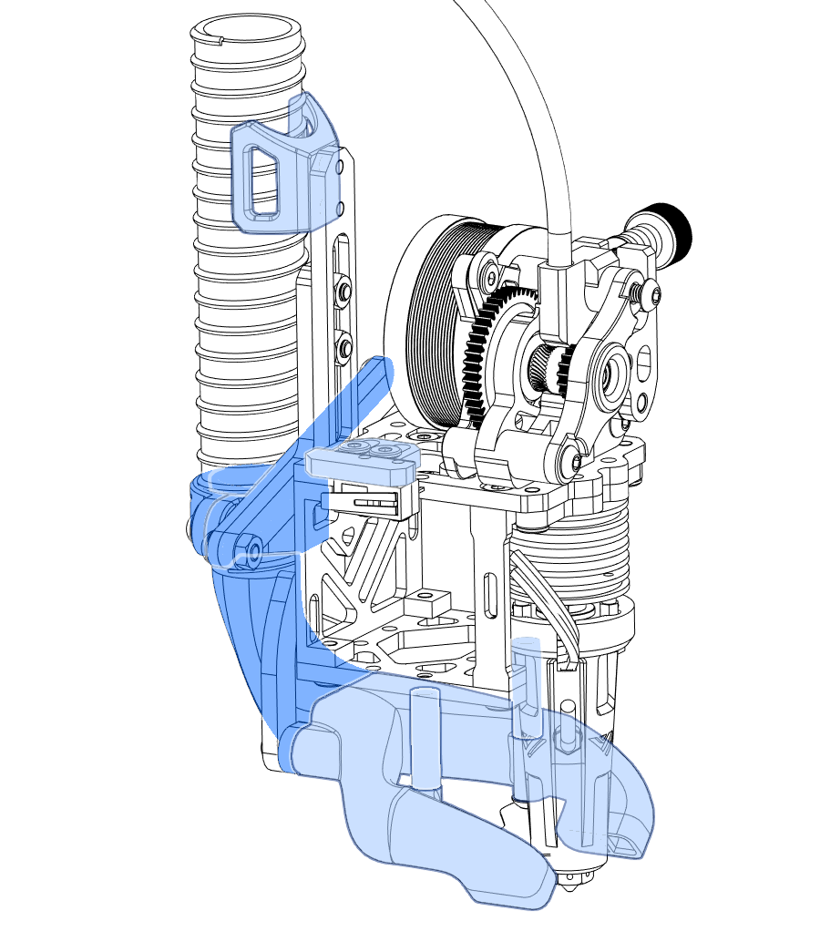
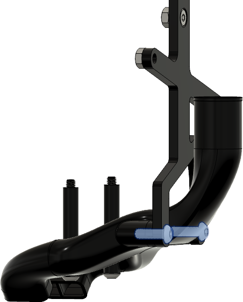
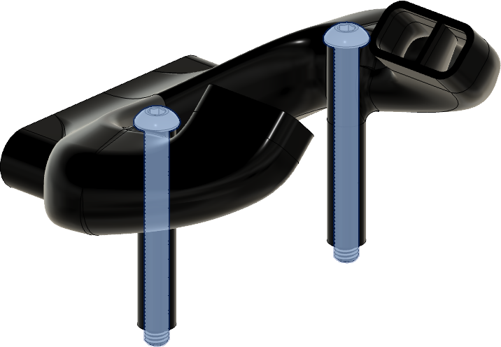
Important
The front arms need to be installed like shown in the picture, be careful otherwise the belt routing will not work.
 |
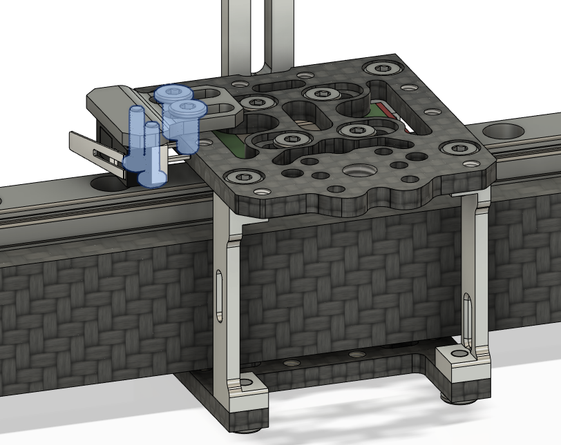
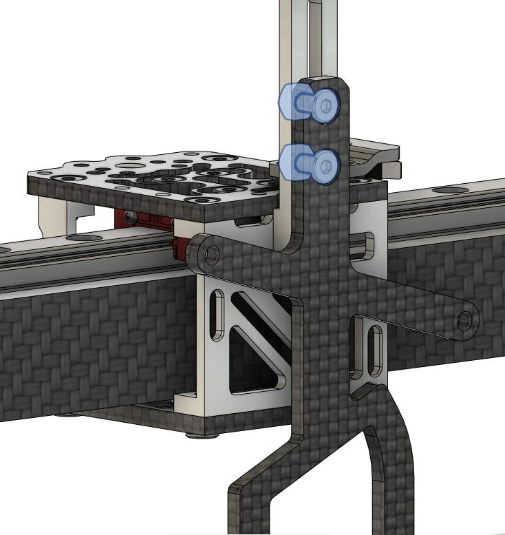
• Screw on the top plate to the MGN carriage with the four M3 x 5mm screws • Install the back part from step 1 to the top plate with the two M3 x 6mm screws • Install the front spacers with two M3 x 6mm screws • Install the bottom plate to the assembly with four M3 x 6mm screws. |
Step 3
Required
• Box 6 - M3 x 6mm
• Box 6 - M2 x 8mm
| Part | Location |
|---|---|
| M3 x 6mm Quantity: 2 |
Layer: 3 Box: VZ330 Box 6 |
| M2 x 8mm Quantity: 2 |
Layer: 3 Box: VZ330 Box 6 |
 |
• Screw on the printhead cable holder with two M3 x 6mm screws • Attach the printed cable holder to the top with two M3 x 6mm screws. |
Step 4
Required
• Box 6 - M3 x 6mm
• Box 6 - M3 nut
| Part | Location |
|---|---|
| M3 x 6mm Quantity: 2 |
Layer: 3 Box: VZ330 Box 6 |
| M3 nut Quantity: 2 |
Layer: 3 Box: VZ330 Box 6 |
| Part from step 3 | Part from step 3 |
| Fan holder | STL |
 |
• Screw on the printhead fan holder to the assembly with two M3 x 6mm screws and M3 nuts. |
Step 5
Required
• Box 2
| Part | Location |
|---|---|
| GT2 belt Quantity: 1 |
Layer: 1 Box: VZ330 Box 2 |
| Belt clips Quantity: 2 |
STL |
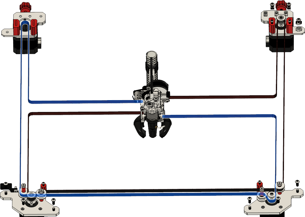 |
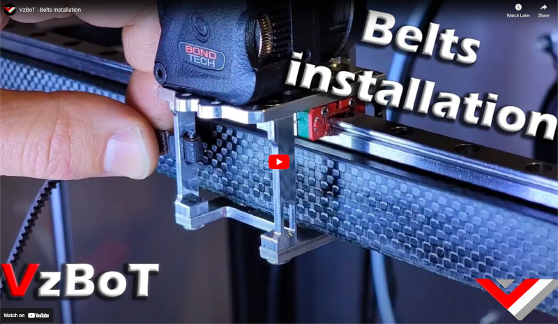
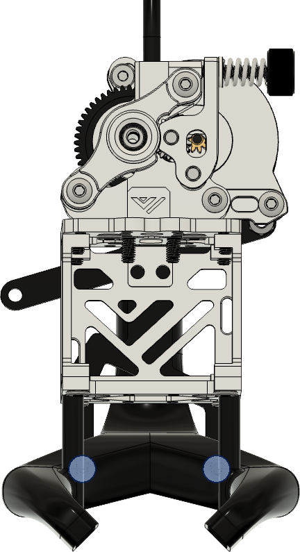
• Insert the first belt like so ( watch the video linked below for more details.) |
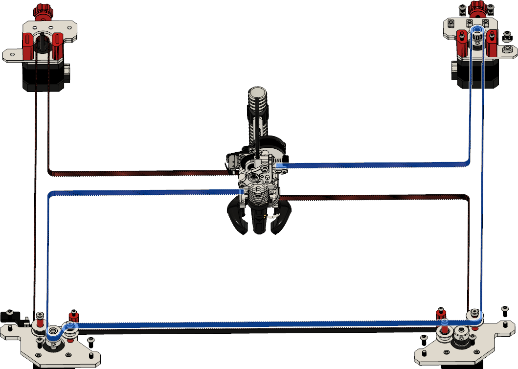 |
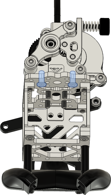
• Insert the second belt like so ( watch the video linked below for more details.) |
 |
• Make sure the motor’s in the back are in the loosest position possible, moved to the front of the motor mount. |
Step 6
Required
• Box 6 - M3 x 10mm
• Box 6 - M3 x 30mm
| Part | Location |
|---|---|
| M3 x 10mm Quantity: 2 |
Layer: 3 Box: VZ330 Box 6 |
| M3 x 30mm Quantity: 2 |
Layer: 3 Box: VZ330 Box 6 |
| M3 heat insert Quantity: 2 |
self source |
| Fanduct Quantity: 1 |
STL’s |
| xx Quantity: 1 |
STL’s |
 |
• Insert the heat insert’s in the back holes of the fanduct |
 |
• Screw on the fan duct with the cpap connector to the printhead, with the M3 x 10mm screws. |
 |
• Use the printed spacers and the M3 x 30mm screws to secure and stabilize the duct to the printhead. |
Step 7
Required
• Box 6 - M3 x 6mm
 |
| Part | Location |
|---|---|
| M3 x 6mm (ultra low profile ) Quantity: 2 |
Layer: 3 Box: VZ330 Box 6 |
 |
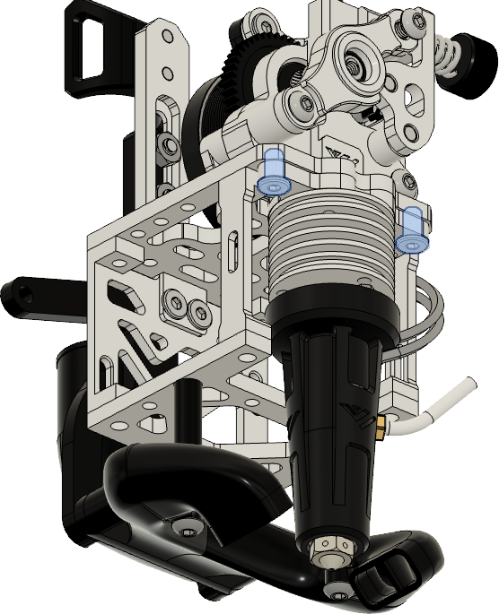
• Attach the preassembled extruder to the printhead with the M3 x 5mm ( ultra low profile ) screws |
Step 8
Required
• Box 6 - M2.5 x 5mm
• Box 6 - M3 x 6mm
• Box C
 |
| Part | Location |
|---|---|
| M2.5 x 5mm (ultra low profile ) Quantity: 2 |
Layer: 3 Box: VZ330 Box 6 |
| M3 x 6mm (ultra low profile ) Quantity: 4 |
Layer: 3 Box: VZ330 Box 6 |
| PTFE tube (22mm) Quantity: 1 |
self source |
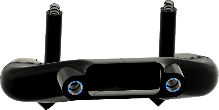
| Goliath Hotend Quantity: 1 |
Layer: 3 Box: VZ330 Box C |
| Adapter plate Quantity: 1 |
Layer: 3 Box: VZ330 Box C |
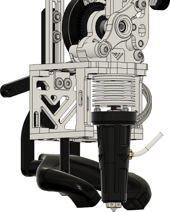
NOTE: Before attaching the Goliath hotend to the printhead, make sure you have applied thermal paste between the heatbreak and the heatsink.
Also make sure that all screws are tightn and that the heatbreak is tight against the heater block. More info can be found on the Goliath docs:
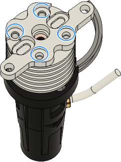 |
• Attach the adapter plate to the goliath hotendend with the M2.5 x 5mm 5 mm screws. |
 |
• Slide on the printed fan holder to the goliath hotend • Insert the 22mm pfte tube into the goliath on top • Screw on the goliath to the printhead with the M3 x 6mm |