4. Bottom and rear panels
Overview
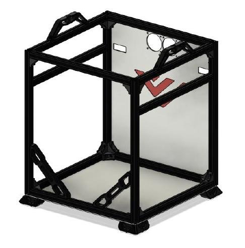
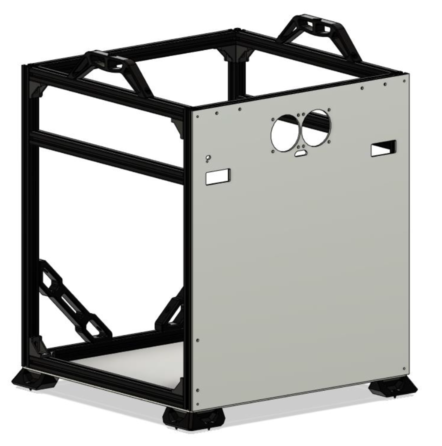
A full panel kit is available at F3D-racing’s shop. We recommend getting that over drilling the holes by hand because it is really difficult to get all holes in exactly the right position. If you want to drill the holes yourself, it is recommended to use the CAD as reference. For the AWD variant, the rear panel must have cutouts at the idler/ motor mount as shown above. These are to reach the motor pulley to be able to synchronize the motors!
BOM
| Material | Quantity | Notes |
|---|---|---|
| M4 6-8mm | 20* | |
| M4 20mm | 8 | - |
| M4 25mm | 4 | - |
| M4 t-nuts | 20* | - |
| M5/M6 25mm | 4 | Depending on the extrusion type |
| Wood screws | 8 | Optional, to screw the printer down to a surface |
| 415x425x3mm aluminium | 1 | Optionally thickness, 1.5mm also possible |
| 425x470x3mm aluminium | 1 | Optionally thickness, 1.5mm also possible |
STL’s
| File name | Amount to print |
|---|---|
| VzBoT Foot | 4 |
| Foot scalable spacer (optional) | 4 |
Step 1
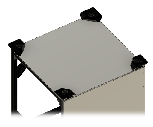
Mount all hardware in the backpanel and put the panel on the frame. It is easiest to start tightening starting in the middle of each side and work your way outwards to prevent the panel from bulging.
Step 2
Insert all hardware in the printed feet and mount the rubber feet inside. When scaling the printed spacer make sure to get it to the height your rubber feet sticks out about 1-2mm out of the printed feet.
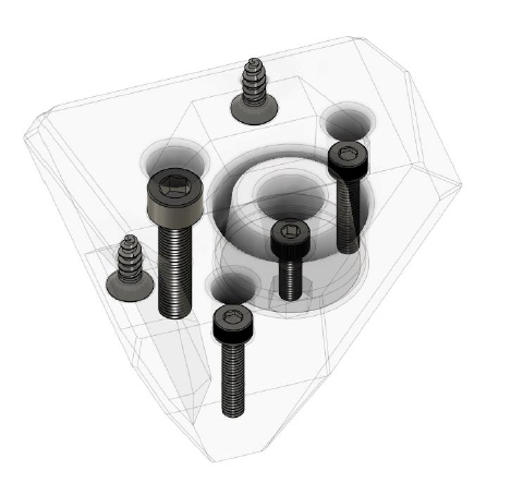
Step 3
Mount the feet and all hardware to the bottom panel. Next up mount the bottom panel to the frame.