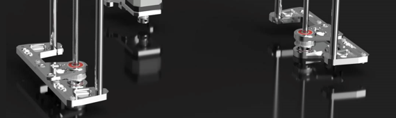
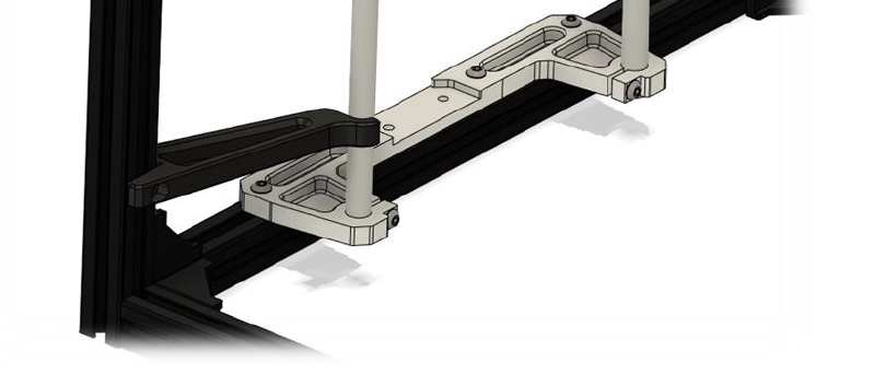
3.1 Lower rod & leadscrew bracket
 |
Part’s
| Part | Location | Comment |
|---|---|---|
| M4 x 10mm Quantity: 4 |
Layer: 3 Box: VZ330 Box 6 |
|
| M4 x 12mm Quantity: 16 |
Layer: 3 Box: VZ330 Box 6 |
|
| M4 t-nut Quantity: 20 |
Layer: 3 Box: VZ330 Box 6 |
|
| M4 rollin t-nut Quantity: 4 |
Box: VZ330 Box 6 |  |
| 10mm rods ( 500mm ) Quantity: 4 |
Layer: 2 |  |
| Belt GT2 closed ( 1100mm ) Quantity: 1 |
Layer: 2 Box: VZ330 Box 2 |
picture |
| Leadscrew TR8 ( 500 mm ) Quantity: 2 |
Layer: 2 |  |
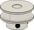
| GT2 40 teeth Quantity: 2 |
Layer: 2 Box: VZ330 Box 2 |
 |
| z bracket Quantity: 2 |
Layer: 1 | 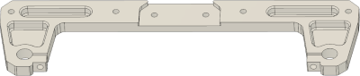 |
| Lower leadscrew mount Quantity: 2 |
Layer: 1 | 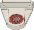 |
| Upper leadscrew mount Quantity: 2 |
Layer: 1 | 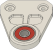 |
STL’s
You can click on the object you wanna print on the plate and the corresponding STL will open up.

Step 1
Follow these instructions once for each side
Required
• Box 6 - M4 x 12mm
 |
| Part | Location |
|---|---|
| z bracket Quantity: 2 |
Layer: 1 |
| M4 x 12mm Quantity: 4 |
Layer: 3 Box: VZ330 Box 6 Bag: M4 Bagnumber: 13/16 |
| Rods ( 10mm ) Quantity: 4 |
Layer: 1 |
 |
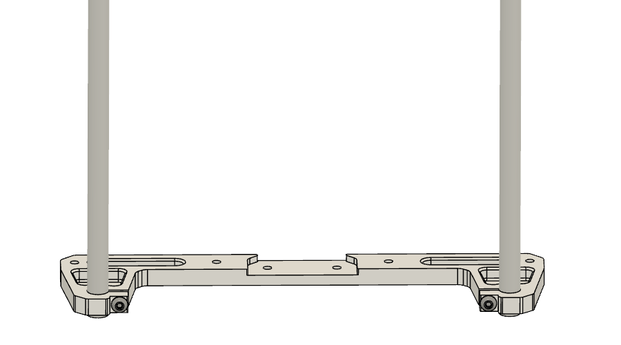
• Align the rod flush with the bottom of the z bracket |
 |
• Tighten the M4 x 12mm screw |
Step 2
Follow these instructions once for each side
Required
• Box 6 - M4 x 12mm
• Box 6 - M4 t-nut
• Box 6 - M4 rollin t-nut
 |
| Part | Location |
|---|---|
| z bracket Quantity: 2 |
Layer: 1 |
| M4 x 12mm Quantity: 8 |
Layer: 3 Box: VZ330 Box 6 Bag: M4 Bagnumber: 13/16 |
| M4 t-nut Quantity: 8 |
Layer: 3 Box: VZ330 Box 6 Bag: M4 Bagnumber: 2/16 |
| M4 rollin t-nut Quantity: 4 |
Box: VZ330 Box 6 Bag: M4 Bagnumber: 3/16 |
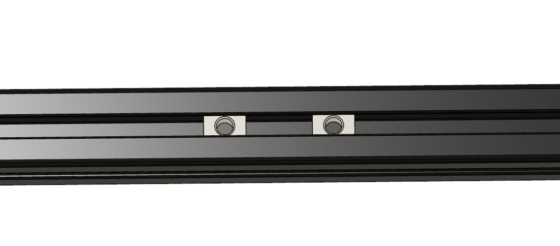 |
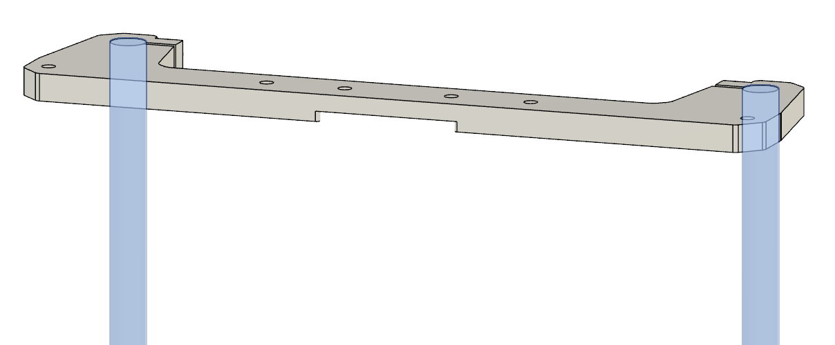
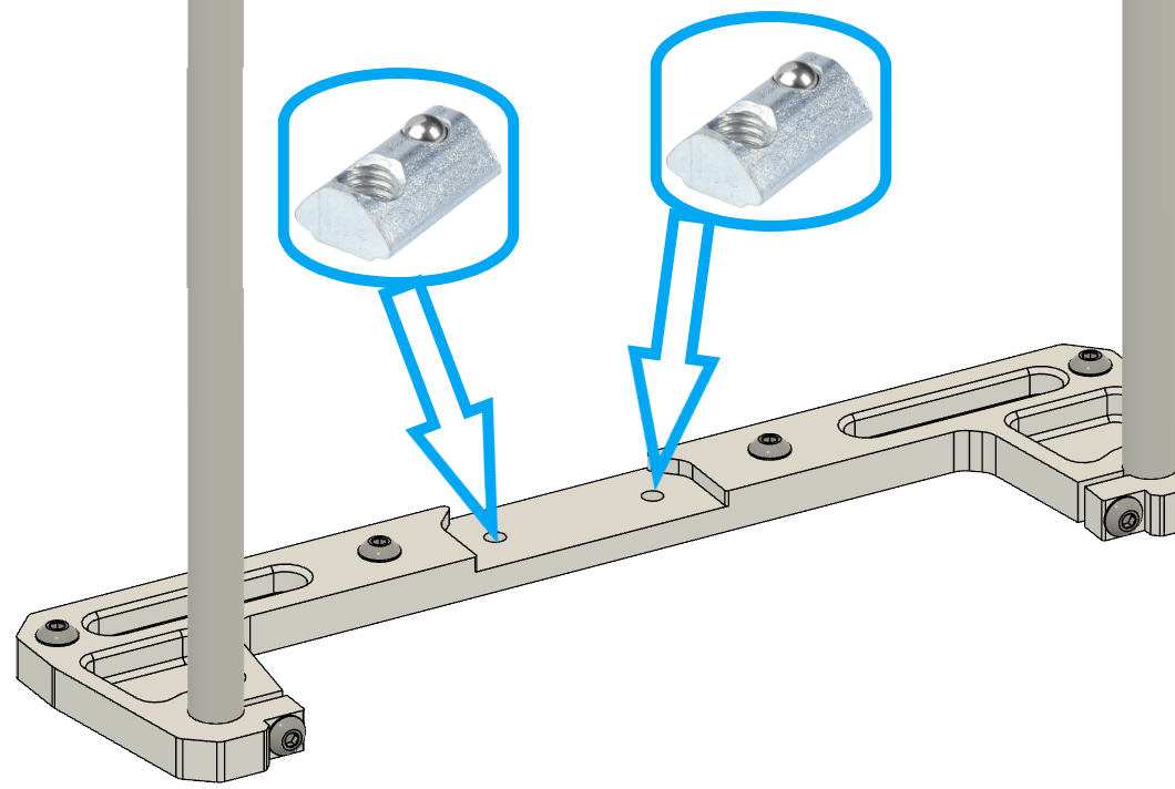
• Insert rollin t-nut in the extrusion below the middle two holes |
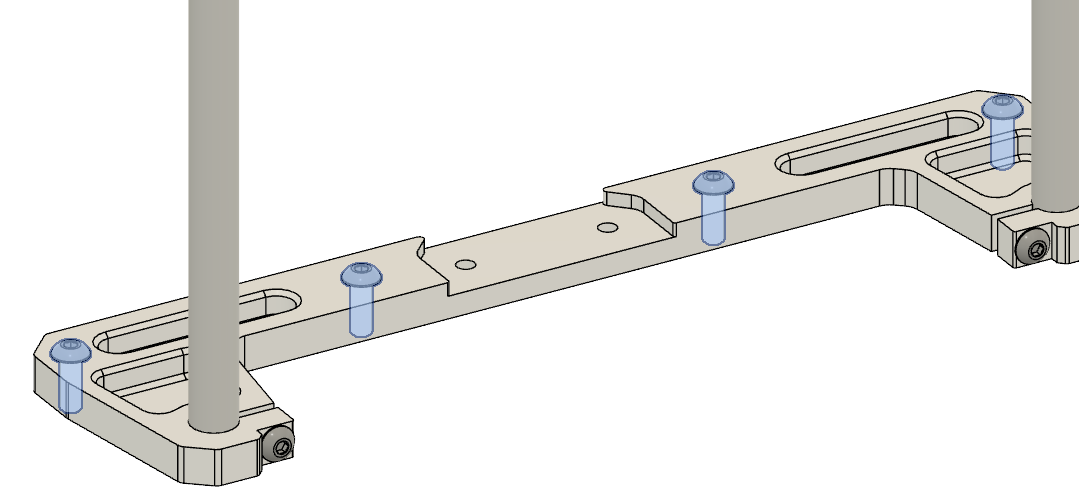 |
• Attach M4 x 12mm + t-nut to the z bracket • Tip:Drop in the plate and add in the two screws for now in the two holes in the middle for the rollin t-nuts so they move with the part if you move it around. |
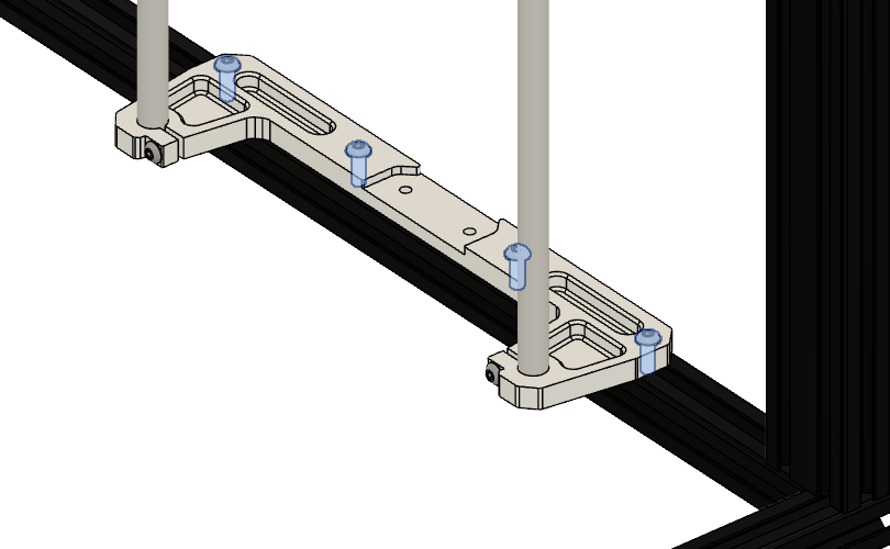 |
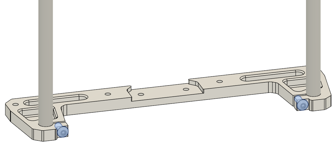
• Tighten the M4 x 12mm screw loosly, we need to align the z bracket |
 |
• Align the front rod with the z-alignment tool. Use M4x10 and t-nuts for the tool. • tighten the M4 x 12mm screws, when it’s aligned |
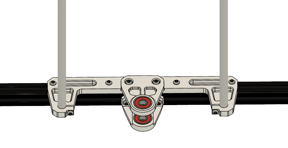
Step 3
Follow these instructions once for each side
Notes
Required
• Box 6 - M4 x 10mm
• Box 6 - M4 t-nut
 |
| Part | Location |
|---|---|
| Lower leadscrew mount Quantity: 2 |
Layer: 1 |
| M4 x 10mm Quantity: 4 |
Layer: 3 Box: VZ330 Box 6 Bag: M4 Bagnumber: 13/16 |
| M4 t-nut Quantity: 4 |
Layer: 3 Box: VZ330 Box 6 Bag: M4 Bagnumber: 2/16 |
 |
• Attach M4 x 10mm + t-nut to the lower leadscrew mount |
 |
• Insert lower leadscrew mount to bottom extrusion • Tighten the M4 x 10mm screw loosly, and center the lower leadscrew mount • We will align the parts in Step 5 |
Step 4
Follow these instructions once for each side
Required
• Box 6 - M4 x 12mm
 |
| Upper leadscrew mount Quantity: 2 |
Layer: 1 |
| M4 x 12mm Quantity: 4 |
Layer: 3 Box: VZ330 Box 6 Bag: M4 Bagnumber: 13/16 |
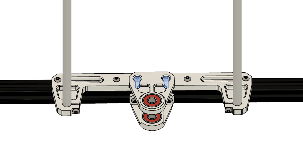 |
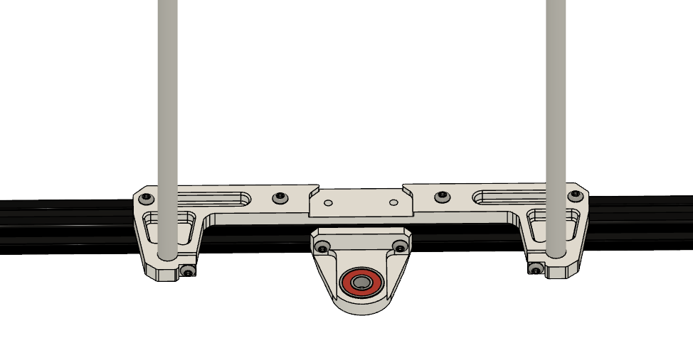
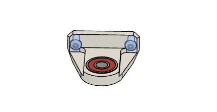
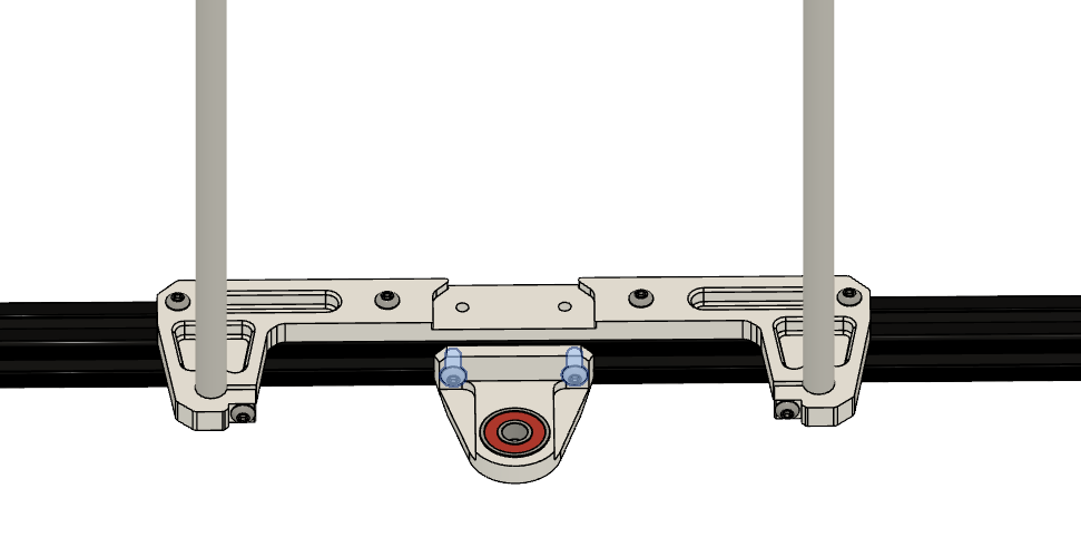
• Insert upper leadscrew mount to single z bracket • Tighten the M4 x 12mm screw loosly, and center the lower leadscrew mount • Use the leadscrews or a drill bit/similar tool (with 8mm diameter), put it through the two bearing’s and prealign the two mounts • We will align the parts in Step 5 |
Step 5
Follow these instructions once for each side
Required
• Box 2
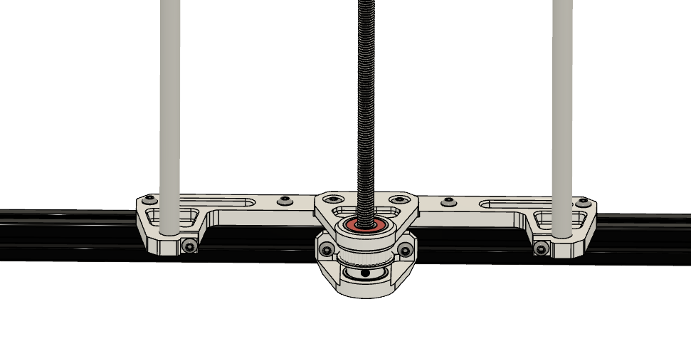 |
| Leadscrew Quantity: 2 |
Layer: 2 |
| GT2 40 teeth idler Quantity: 2 |
Layer: 2 Box: VZ330 Box 2 |
| Closed GT2 belt ( 1100mm ) Quantity: 1 |
Layer: 2 Box: VZ330 Box 2 |
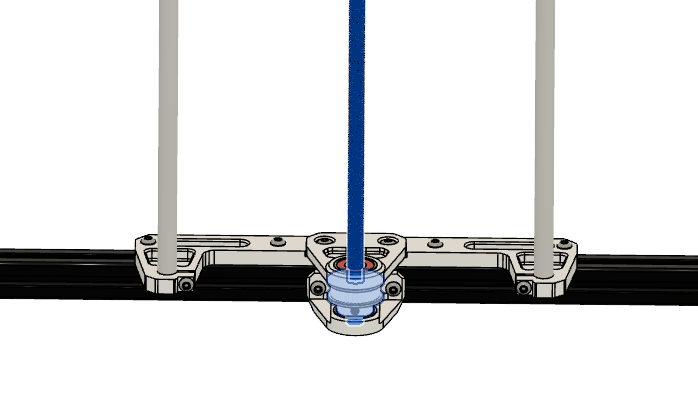 |
• Insert closed GT2 belt between lower and upper leadscrew mount • Insert GT2 40 tooth idler between lower and upper leadscrew mount (the beld should be around the idler ) • Insert leadscrew • Secure leadscrew with grub screws of the GT2 idler (leadscrew shouldn’t rub on the ground) • Check that leadscrew is straight and tighten upper and lower leadscrew bracket |