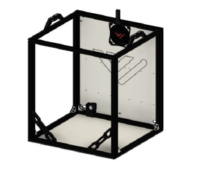
5. Bottom and rear panels
 |
Parts
| Material | Quantity | Notes |
|---|---|---|
| M4 6-8mm | 20 | |
| M4 20mm | 8 | |
| M4 25mm | 4 | |
| M4 t-nuts | 20 | |
| Wood screws | 8 | Optional, to screw the printer down to a surface |
| 570x500x3mm aluminium | 1 | Optionally thickness, 1.5mm also possible |
| 530x500x3mm aluminium | 1 | Optionally thickness, 1.5mm also possible |
STL’s
| File name | Amount to print |
|---|---|
| VzBoT Foot | 4 |
| Scalable Spacer “Optional” | 4 |
Step 1
| Part | Location |
|---|---|
| M4 sliding t-nut Quantity: x |
Layer: 3 Box: VZ330 Box 6 |
| M4 x 8mm Quantity: x |
Layer: 3 Box: VZ330 Box 6 |
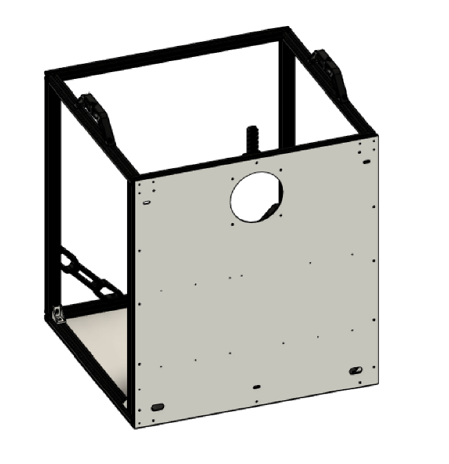 |
• Mount the PSU to the backplate first • Insert sliding t-nuts • Align them with the holes of the panel • Start screwing the panel down from the middle to the outside holes. |
Step 2
| Part | Location |
|---|---|
| Rubber feet Quantity: 4 |
- |
| M4 x 20mm Quantity: 12 |
Layer: 3 Box: VZ330 Box 6 |
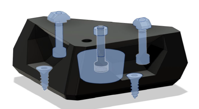 |
• Insert all hardware in the printed feet • The rubber feet should stick out 1-2 mm ( scale the spacer accordingly ) |
Step 3
| Part | Location |
|---|---|
| M4 sliding t-nut Quantity: x |
Layer: 3 Box: VZ330 Box 6 |
| M4 x 8mm Quantity: x |
Layer: 3 Box: VZ330 Box 6 |
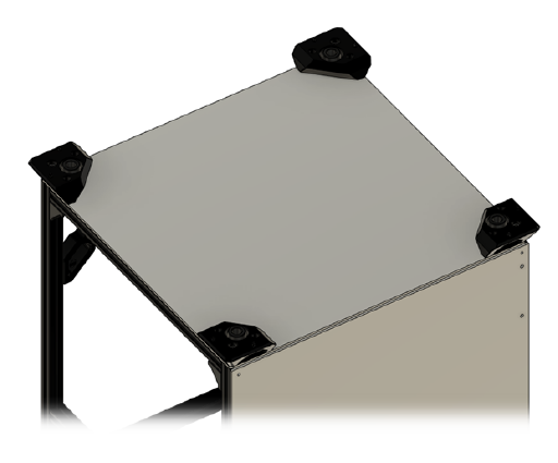 |
• Insert all M4 sliding t-nuts in the frame and align them with the holes of the plate • Mount plate and feet to the frame. |